Restructure
The Restructure structural pattern is a derivative of the Reconfiguration architectural pattern and the Fault Treatment and Fault Recovery strategy patterns in the original resilience design pattern specification (Fig. 32) [B24]. It offers detection, containment, and mitigation without restoring previously preserved state, employing redundancy, or self-masking or self-correcting illegal system state. The following describes the Pattern and its application in the System Scope and in the Service Scope of the INTERSECT federated ecosystem for instrument science. Note that the Pattern description uses the terms system, subsystem, and service in an abstract way, while the System Scope and the Service Scope map those terms to the INTERSECT federated ecosystem.
Pattern
- Problem
A hardware or software error or subsystem failure due to a physical fault (e.g., wear-out or destruction) or a design fault (e.g., resource underprovisioning) causes a software, such as a service, to experience an error or failure.
- Context
The pattern applies to a system that has the following characteristics:
The system is deterministic, i.e., forward progress of the system is defined in terms of the input state to the system and the execution steps completed since system initialization.
The system has well-defined parameters that enable a monitoring system to discover the presence of an existing or future fault, error, or failure in the behavior of the monitored system.
The interaction between the monitored and monitoring systems is bounded in terms of time.
The monitoring system has the capability to readily analyze the behavior of the monitored system to detect or predict a fault, error, or failure.
The system is able to be partitioned into logical subsystems, where altering the interconnection between the subsystems enables the system to remain operational.
- Forces
The interactions between the monitoring and monitored systems may interfere with the operation of the monitored system, specifically its performance.
While the frequency and duration of these interactions must be minimized to reduce the monitoring overhead, the interactions must be able to detect or predict a fault, error, or failure in the monitored system.
The diagnostic resolution, i.e., the degree of accuracy of the fault diagnosis, must be high to be effective.
The ability of the system to alter the interconnection among subsystems must permit system operation that is functionally equivalent to the fault, error, or failure-free operation of the system.
The restructuring may force the system to operate at a lower level of performance.
- Solution
The pattern alleviates the impact of a fault, error, or failure on system operation by changing the interconnection between the subsystems in the overall system. It has a detection component and an additional containment and mitigation component that acts upon the notification from the detection component.
The detection component enables the discovery of an existing or future fault, error, or failure in the system. It enables its containment and mitigation by notifying the system about it with location and type information. The solution requires a monitoring system, which may be a subsystem of the monitored system or an external independent system, to observe key parameters of the monitored system and to notify the monitored system when these parameters deviate. This pattern does not specify the detailed method of detection or prediction.
The containment and mitigation component acts upon the notification from the detection component by modifying the interconnection between the \(N\) subsystems in the overall system to permanently isolate (exclude) the subsystem affected by the predicted or detected fault, error, or failure. The system assumes an \(N-1\) subsystem configuration in response to a notification, which is characterized by its own interconnection topology and retains functional equivalency with the original system configuration. The components of this pattern are illustrated in Fig. 39.

Fig. 39 Restructure pattern components
- Capability
A system using this pattern is able to continue to operate in the presence of a non-permanent fault, error, or failure with some interruption. This pattern provides detection/prediction, containment, and mitigation of a future or existing fault, error, or failure in the system by changing the interconnection between the subsystems in the overall system to a functionally equivalent configuration, permanently isolating (excluding) the affected subsystem. The flowchart of the pattern is shown in Fig. 40, the state diagram in Fig. 41, and its parameters in Table 6.
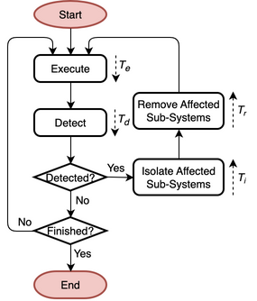
Fig. 40 Flowchart
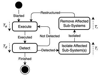
Fig. 41 State diagram
Table 6 Restructure pattern parameters Parameter
Definition
\(T_{e}\)
Time to execute system progress
\(T_{d}\)
Time to detect or predict a fault, error or failure
\(T_{i}\)
Time to isolate the affected subsystem(s)
\(T_{r}\)
Time to remove the affected subsystem(s)
- Protection Domain
The protection domain extends to the monitored system’s state that is not lost due to a subsystem exclusion and to all of its resources that are able to be operate correctly after a restructuring.
- Resulting Context
A fault, error, or failure is prevented from affecting the correct operation of the system. While functional equivalency to the original system configuration is maintained through reconfiguration, progress in the system may be lost. The system is interrupted during reconfiguration in response to a detected or predicted fault, error, or failure, but is not interrupted during fault-, error-, and failure-free operation. The restructuring may force the system to operate at a lower level of performance. After reconfiguration, the system’s ability to prevent a fault, error or failure from affecting the correct operation of the system remains the same if it retains the capability to assume an \(N-1\) system configuration with functional equivalency (where \(N\) is the new number of subsystems after the previous reconfiguration).
The pattern may be used in conjunction with other patterns that provide containment and mitigation in a complementary fashion, where some error/failure types are covered by the other pattern(s) and the pattern covers for the remaining error/failure types.
- Performance
In the case when the monitoring system is not a part of the monitored system, the monitoring system doesn’t impact the task’s total execution time \(T_{E}\). The error/failure-free performance \(T_{f=0}\) is \(T_{E}\).
When the monitoring system is a part of the monitored system, the failure-free performance \(T_{f=0}\) of the pattern is defined by the task’s total execution time without any resilience strategy \(T_{E}\) and the time to detect or predict a fault, error or failure \(T_{d}\) with the total number of input-execute-output cycles \(P\).
\[\begin{aligned} T_{f=0} = T_{E} + P t_{d} \end{aligned}\]The performance under errors/failures \(T_{f!=0}\) is defined by \(T_{f=0}\), plus the time to isolate the affected subsystem(s) \(T_{i}\) and the time to remove the affected subsystem(s) \(T_{r}\), for each of the encountered faults, errors or failures \(N\). Assuming constant times for \(T_{i}\) and \(T_{r}\), \(T_{f!=0}\) can be defined as:
\[\begin{aligned} T_{f!=0} = T_{f=0} + N (T_{i} + T_{r}) \end{aligned}\]- Reliability
Given that the pattern enables the resumption of correct operation after an error or failure, the reliability of a system employing it is defined by errors and failures that are not handled by the pattern, such as failures of the persistent storage. The reliability after applying the pattern \(R(t)\) can be obtained using the performance under failure \(T\) and the failure rate \(\lambda_{u}\) (or its inverse, the mean-time to interrupt (MTTI), \(M_{u}\)) of the unprotected part of the system.
\[\begin{aligned} R(t) = e^{-\lambda_{u} T} = e^{-T/M_{u}} \end{aligned}\]- Availability
The availability of the pattern can be calculated using the task’s total execution time without the pattern \(T_{E}\) and performance under errors/failures \(T_{f!=0}\). \(T_{E}\) is the planned uptime (PU) \(t_{pu}\). \(T_{f!=0}\) is the planned uptime (PU) \(t_{pu}\), the scheduled downtime (SD) \(t_{sd}\), and the unscheduled downtime (UD) \(t_{ud}\).
\[\begin{aligned} A = \frac{T_{E}}{T_{f!=0}} = \frac{t_{pu}}{t_{pu}+t_{ud}+t_{sd}} \end{aligned}\]
- Examples
Unhealthy, erroneous, or failed system resources, such as compute nodes or general-purpose computing graphics processing unit (GPGPU) memory pages [B51], are removed from the system’s pool of resources though restructuring. A programming model, such as the proposed extension to the Message Passing Interface (MPI) standard [B52], permits an application to restructure the programming environment to handle resource failures.
- Rationale
The pattern prevents an existing or future fault, error, or failure from affecting the correct operation of the system through changing the interconnection between \(N\) subsystems in the overall system. It relies on the ability to assume an \(N-1\) functionally equivalent system configuration in response to a detected or predicted fault, error, or failure that retains functional equivalency with the original system configuration. The pattern may perform proactive actions, such as restructuring the system or subsystem before a fault, error, or failure impacts its operation, or reactive actions, such as restructuring the system or subsystem upon such an event.
Progress in the system may be lost. Fault, error, or failure detection/prediction is part of the pattern. The containment and mitigation offered by this pattern are independent from the type of fault, error, or failure. The pattern has some design complexity due to the need to partition the system into logical subsystems. It has low dependence on a system’s architecture.
System Scope
In the context of INTERSECT Systems, Subsystems, and Services, this pattern can be applied to INTERSECT systems and subsystems. It would be primarily applied to an entire infrastructure system and its subsystems, but it could also be applied an entire logical system that spans across multiple infrastructure systems. It could be applied to a logical subsystem of an infrastructure system only. The pattern could also be applied across multiple infrastructure systems and their entire logical systems or across multiple logical systems.
Service Scope
In the context of INTERSECT Systems, Subsystems, and Services, this pattern can be applied to an INTERSECT service. If it is applied to a group of services, then this is typically within the System Scope. However, it could also be applied to interconnected services, such as to services participating in the same campaign.
Microservice Scope
In the context of the INTERSECT Microservices Architecture, this pattern can be applied to an INTERSECT microservice. If it is applied to a group of microservices, then this is typically within the Service Scope.