Active/Standby
The Active/Standby structural pattern is a derivative of the Redundancy architectural pattern and the Compensation strategy pattern in the original resilience design pattern specification (Fig. 32) [B24]. It offers detection, containment and mitigation with continuous operatation in the presence of an error or failure, and with none-to-significant interruption and loss of progress. The following describes the Pattern and its application in the System Scope and in the Service Scope of the INTERSECT federated ecosystem for instrument science. Note that the Pattern description uses the terms system, subsystem, and service in an abstract way, while the System Scope and the Service Scope map those terms to the INTERSECT federated ecosystem.
Pattern
- Problem
A hardware error or subsystem failure due to a physical fault (e.g., wear-out or destruction) causes a software, such as a service, to experience an error and potentially a subsequent failure.
- Context
The pattern applies to a system that has the following characteristics:
The system is deterministic, i.e., forward progress of the system is defined in terms of the input state to the system and the execution steps completed since system initialization.
The system has a modular design that has a well-defined scope and a set of inputs and outputs.
- Forces
The pattern introduces a resource requirement (storage space, computational capability, etc.) penalty independent of whether an error or failure occurs during system operation or not.
The pattern may introduce an execution time penalty when an error or failure occurs during system operation.
The scope and strength of the redundancy employed by the pattern determine its execution time and resource requirement overhead.
- Solution
The pattern enables the continuous correct operation of a system impacted by an error or failure. It supports resilient operation by applying redundancy to system state and to system resources. This redundancy is in the form of \(N\) functionally identical replicas, using redundancy in space and potentially in time. The pattern requires very well defined input and output to permit replication. The pattern can operate in the following modes:
- Active/Hot-Standby
One active system performs the system’s operations, while one or more standby replica systems perform the same operations or obtain an instant and consistent copy of the system state from the active system on change. If the standby systems perform the same operations, input is replicated to and processed by all standby systems. If the standby systems obtain an instant and consistent copy of the system state, the active system processes the input and system state is replicated upon change to all standby systems. This may be performed using a reliable communication protocol, such as a total order broadcast, or a shared stable storage, such as a shared hard disk or a replicated block device. The output is provided only by the active system. The standby systems monitor the active system for any error or failure, such as using a heartbeat. Upon a detected error or failure, a fail-over is performed from the active system to one of the standby systems, making that standby system to become the active system. The fail-over causes only very minimal interruption and no loss of system progress.
- Active/Warm-Standby
One active system performs the system’s operations, while one or more standby replica systems obtain a consistent copy of the system state from the active system in regular intervals. The active system processes the input and system state is replicated in regular intervals to all standby systems. This may be performed using a reliable communication protocol, such as a total order broadcast, or a shared stable storage, such as a shared hard disk or a replicated block device. The output is provided only by the active system. The standby systems monitor the active system for any error or failure, such as using a heartbeat. Upon a detected error or failure, a fail-over is performed from the active system to one of the standby systems, making that standby system to become the active system. The fail-over causes only very minimal interruption. However, system progress between the last system state replication and the error or failure is lost.
- Active/Cold-Standby
One active system performs the system’s operations, while one or more standby replica systems are not operating at all. The active system processes the input and provides the output. The active system is monitored for any error or failure by either an external system, such as using a heartbeat, or by a human. Upon a detected error or failure, a fail-over is performed from the active system to one of the standby systems, making that standby system to become the active system. The fail-over can cause substantial interruption, as it may be performed by a human and not automatically by the external monitoring system. Since there is no state replication, all system progress is lost.
The components of this pattern are illustrated in Fig. 57.
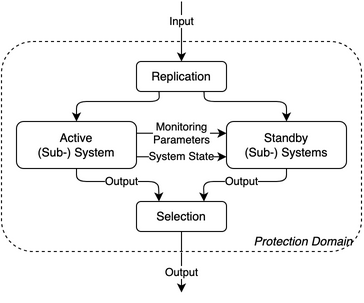
Fig. 57 Active/Standby pattern components
- Capability
A system using the pattern is able to continue to operate in the presence of an error or failure with none-to-significant interruption and loss of progress, depending on the active/standby mode. This pattern provides error and/or failure detection and containment in the system by monitoring the active system. The pattern provides mitigation of an error or failure in the system by applying redundancy to system state and system resources, such that the system continues to operate correctly in the presence of such an event. The flowchart of the pattern is shown in Fig. 58, the state diagram in Fig. 59, and its parameters in Table 12.
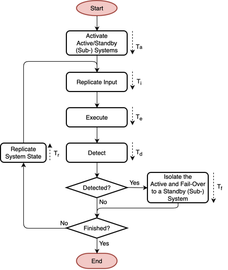
Fig. 58 Flowchart
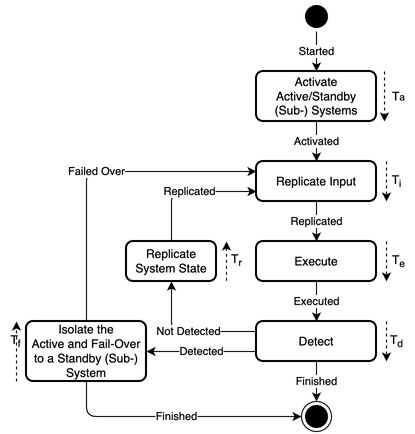
Fig. 59 State diagram
Table 12 Active/Standby pattern parameters Parameter
Definition
\(T_{a}\)
Time to activate the active and standby (sub-) systems
\(T_{i}\)
Time to replicate the input to the active and standby (sub-) systems
\(T_{e}\)
Time to execute progress on the active (sub-) system
\(T_{d}\)
Time to detect an error in or failure of the active (sub-) system
\(T_{f}\)
Time to isolate the active (sub-) system and fail-over to a standby (sub-) system
\(T_{r}\)
Time to replicate system state from the active (sub-) system to the standby (sub-) systems
- Protection Domain
The protection domain extends to the system state and the system resources that implement the \(N\) functionally identical replica systems.
- Resulting Context
Correct operation is performed despite an error or failure impacting the system. Progress in the system may be lost due to an error or failure, depending on the active/standby mode. The system is not interrupted during error/failure-free operation. It is interrupted when encountering an error or failure. Resource usage in space is increased according to the amount of redundancy employed in the form of \(N\) functionally identical replicas and due to the replication of input and or system state.
A trade-off exists between the amount of redundancy employed and the number of errors and/or failures that can be tolerated at the same time and/or in time. More redundancy tolerates generally more errors and/or failures, but requires either more resources or more execution time.
This pattern may be used in conjunction with other patterns that provide containment and mitigation in a complementary fashion, where some error/failure types are covered by the other pattern(s) and this pattern covers for the remaining error/failure types.
- Performance
The error/failure-free free performance \(T_{f=0}\) of the pattern is defined by the task total execution time without any resilience strategy \(T_{E}\), the time to activate the active and (sub-) standby systems \(T_{a}\), and the time to replicate the input to the active and standby (sub-) systems \(T_{i}\), the time to detect an error in or failure of the active (sub-) system \(T_{d}\), and the time to replicate system state from the active (sub-) system to the standby (sub-) systems \(T_{r}\) with the total number of input-execute-output cycles \(P\).
\[\begin{aligned} T_{f=0} = T_{E} + T_{a} + P (T_{i} + T_{d} + T_{r}) \end{aligned}\]The performance under errors/failures \(T_{f!=0}\) is defined by the failure free performance \(T_{f=0}\) plus the time to isolate the active (sub-) system and fail-over to a standby (sub-) system \(T_{f}\) for each of the errors or failures \(N\). Assuming constant times to isolate the active (sub-) system and fail-over to a standby (sub-) system \(T_{f}\) and a ratio for replication in space vs. in time of \(\alpha\), the performance under errors/failures \(T_{f!=0}\) can be reformulated to:
\[\begin{aligned} T_{f!=0} = \alpha T_{E} + (1 - \alpha) N T_{E} + T_{a} + P (T_{i} + T_{d} + T_{r}) + N T_{f} \end{aligned}\]- Reliability
The reliability \(R(t)\) of a system applying this pattern is defined by the parallel reliability of the \(N\)-redundant execution and the performance under errors/failures \(T_{f!=0}\), assuming constant probabilistic rate \(\lambda_{n}\) of errors and failures for each redundant execution (or its corresponding inverse, the MTTI \(M\)). It can be simplified for redundancy of identical systems \(R_{i}(t)\), assuming an identical constant probabilistic error/failure rate \(\lambda\) (or its corresponding inverse \(M\)).
\[\begin{split}\begin{aligned} R(t) &= 1 - \prod_{n=1}^{N}(1-e^{-\lambda_{n} T_{f!=0}}) = 1 - \prod_{n=1}^{N}(1-e^{-T_{f!=0}/M})\\ R_{i}(t) &= 1 - (1 - e^{-\lambda T_{f!=0}})^{N} = 1 - (1 - e^{-T_{f!=0}/M})^{N} \end{aligned}\end{split}\]- Availability
The availability \(A\) of a system applying this pattern is defined by \(N\)-parallel availability and the performance under failure \(T_{f!=0}\). It can be simplified for redundancy of identical systems \(A_{i}\). If \(T_{a}\), \(T_{i}\), \(T_{d}\), \(T_{r}\), and \(T_{f}\) are small enough, non-identical and identical availability can be simplified further, where \(M_{n}\) (or \(M\)) is the MTTI and \(R_{n}\) (or \(R\)) is the mean-time to recover (MTTR) of each individual system (\(T_{f}\)).
\[\begin{split}\begin{aligned} A &= 1 - \prod_{n=1}^{N} (1 - A_{n})\notag\\ &= 1 - \prod_{n=1}^{N} \left(1 - \frac{T_{E,n}}{T_{n}}\right)\\ A_{i} &= 1 - (1-A)^{N}\notag\\ &= 1 - \left(1 - \frac{T_{E}}{T}\right)^{N} \end{aligned}\end{split}\]\[\begin{aligned} A &= 1 - \prod_{n=1}^{N} \left(1 - \frac{M_{n}}{M_{n} + R_{n}}\right) A_{i} &= 1 - \left(1 - \frac{M}{M + R}\right)^{N} \end{aligned}\]
- Examples
The pattern is typically used for critical hardware or software systems in high-performance computing (HPC) environments. For example, power supplies, voltage regulators, the parallel file system metadata service (MDS) in Lustre [B63], and the SLURM [B64] job and resource manager are often implemented in an active/standby fashion.
- Rationale
The pattern enables a system to tolerate an error or failure through continuation of correct operation after impact. It relies on system state and on system resource redundancy in the form of functionally identical replicas. The pattern performs mostly proactive actions, such as maintaining redundancy. Error or failure detection is part of the pattern in the form of monitoring. The pattern has some design complexity, as input or system state needs to be replicated and the fail-over needs to isolate the previous active system.
System Scope
In the context of INTERSECT Systems, Subsystems, and Services, this pattern can be applied to INTERSECT systems and subsystems. It would be primarily applied to an entire infrastructure system and its subsystems, as opposed to an entire logical system that spans across multiple infrastructure systems. It could be applied to a logical subsystem of an infrastructure system only.
Service Scope
In the context of INTERSECT Systems, Subsystems, and Services, this pattern can be applied to an INTERSECT service. If it is applied to a group of services, then this is typically within the System Scope.
Microservice Scope
In the context of the INTERSECT Microservices Architecture, this pattern can be applied to an INTERSECT microservice. If it is applied to a group of microservices, then this is typically within the Service Scope.